
UHF RFID read-zone design
UHF RFID Antennas
Raylink UHF RFID antennas support controlled read-zone design for portals, conveyors, shelves, workstations, cabinets, production equipment and OEM reader integration.
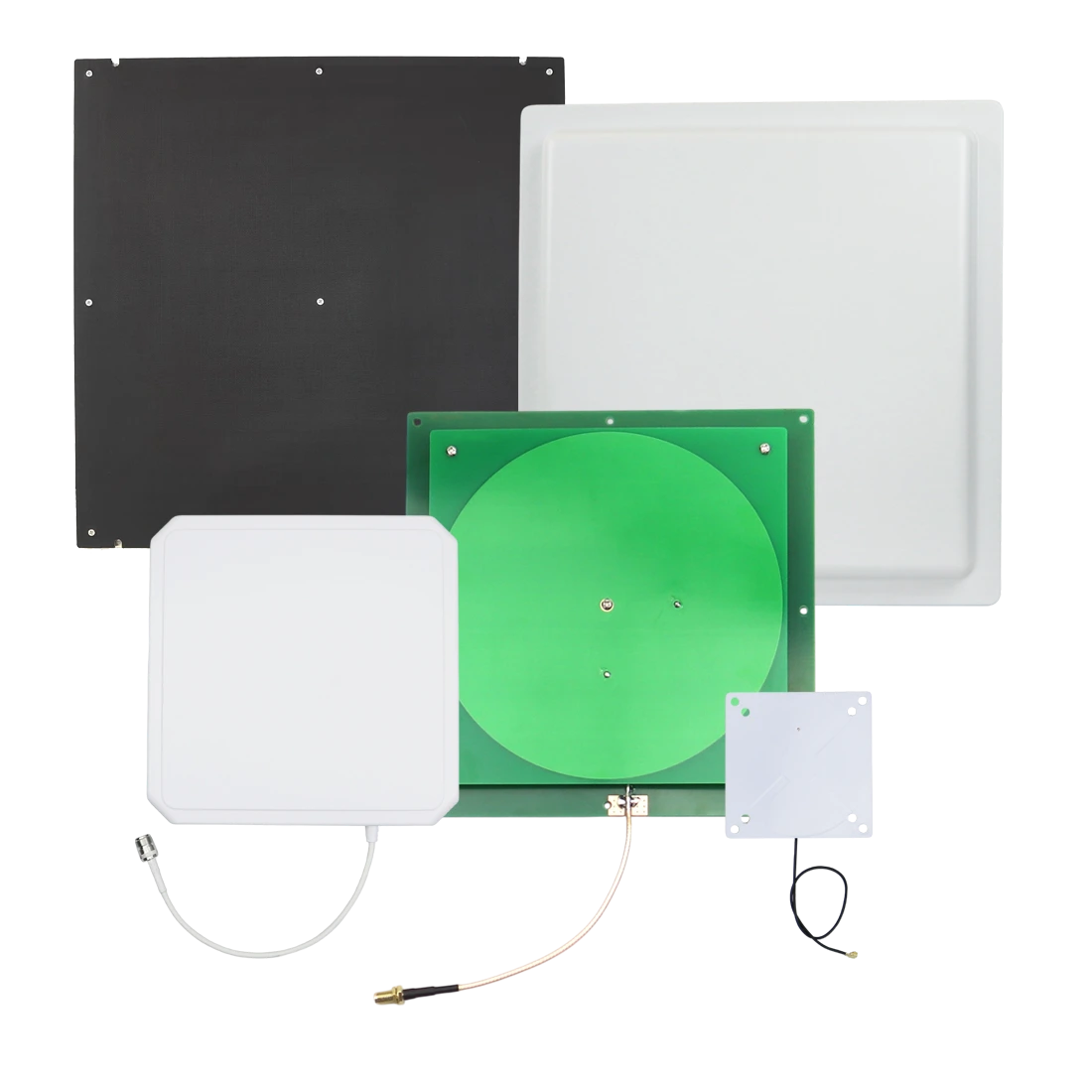
RFID antenna families
Shape the read zone before choosing antenna gain
Choose the antenna according to read-zone shape, tag orientation, mounting geometry, regional frequency, cable path and surrounding materials—not antenna gain alone.
Product lineup
UHF RFID Antenna Families
Start with the required read-zone boundary, then compare field type, polarization, antenna gain, frequency, mounting method, enclosure, connector and feeder-cable path.
Read-zone and polarization options
Antennas for Directional and Controlled Coverage
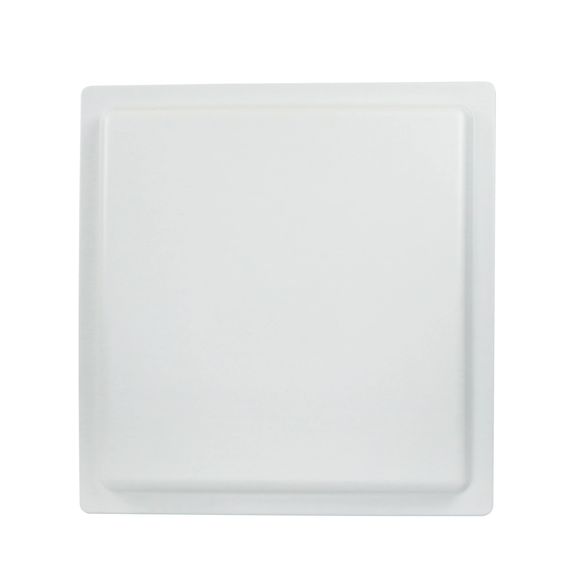
Multi-orientation far-field coverage
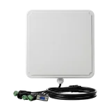
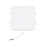
Circularly Polarized UHF RFID Antennas
Circularly polarized UHF RFID antennas are suitable when tag orientation varies as cartons, assets, garments or containers move through the read zone.
- Useful where tag angle cannot be tightly controlled
- Available in compact and higher-gain panel configurations
- Confirm gain, mounting angle, adjacent zones and cable loss
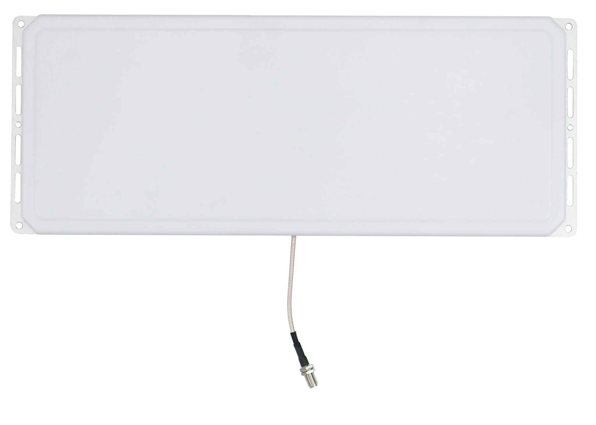
Focused directional coverage
Linearly Polarized UHF RFID Antennas
Linearly polarized UHF RFID antennas provide a focused field when tag orientation and the intended read direction are known and consistently controlled.
- Fits aligned tags on shelves, lanes, fixtures or process carriers
- Supports more deliberate field direction and read-zone shaping
- Confirm tag axis, antenna aim and installation repeatability
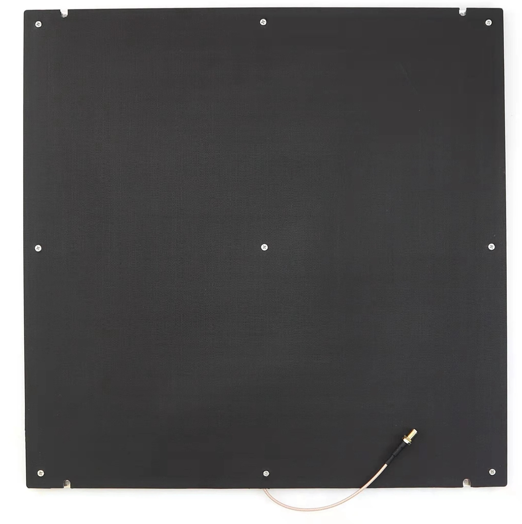
Short controlled UHF read zones
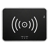
Near-Field UHF RFID Antennas
Near-field UHF RFID antennas are designed for close, controlled item identification where the read boundary matters more than maximum distance.
- Suitable for workstations, verification points and smart cabinets
- Helps reduce reads from items outside the intended zone
- Confirm object gap, tag construction, metal and liquid interaction
OEM and housing configurations
Antennas for Equipment Integration and Installed Read Points
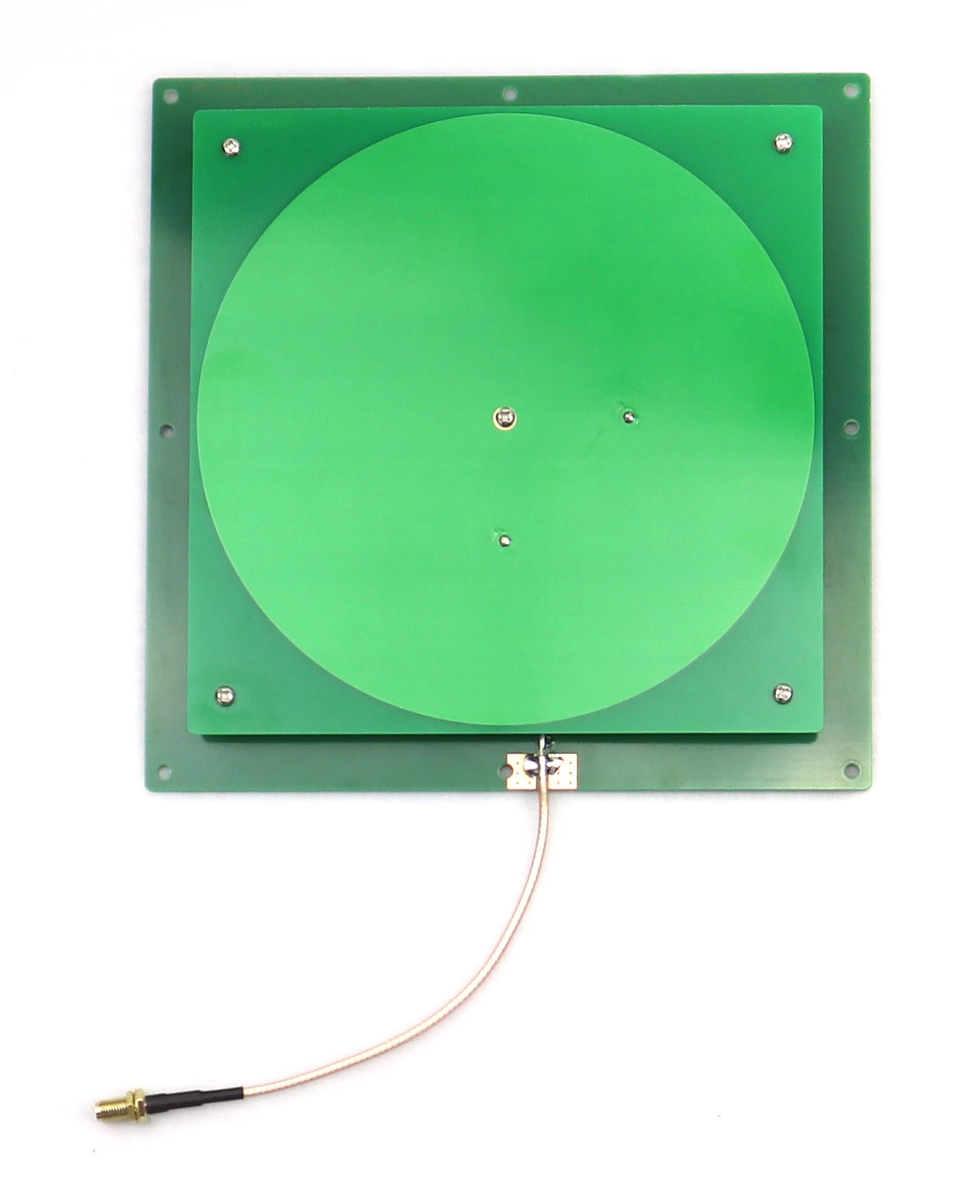
Compact OEM antenna structures
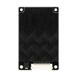
PCB UHF RFID Antennas
PCB UHF RFID antennas provide a compact antenna structure for cabinets, kiosks, machines and OEM readers where the enclosure and installation geometry are controlled by the equipment designer.
- Confirm available footprint, enclosure material and ground plane
- Review feed point, connector, cable path and detuning risk
- Validate the completed device rather than the antenna alone
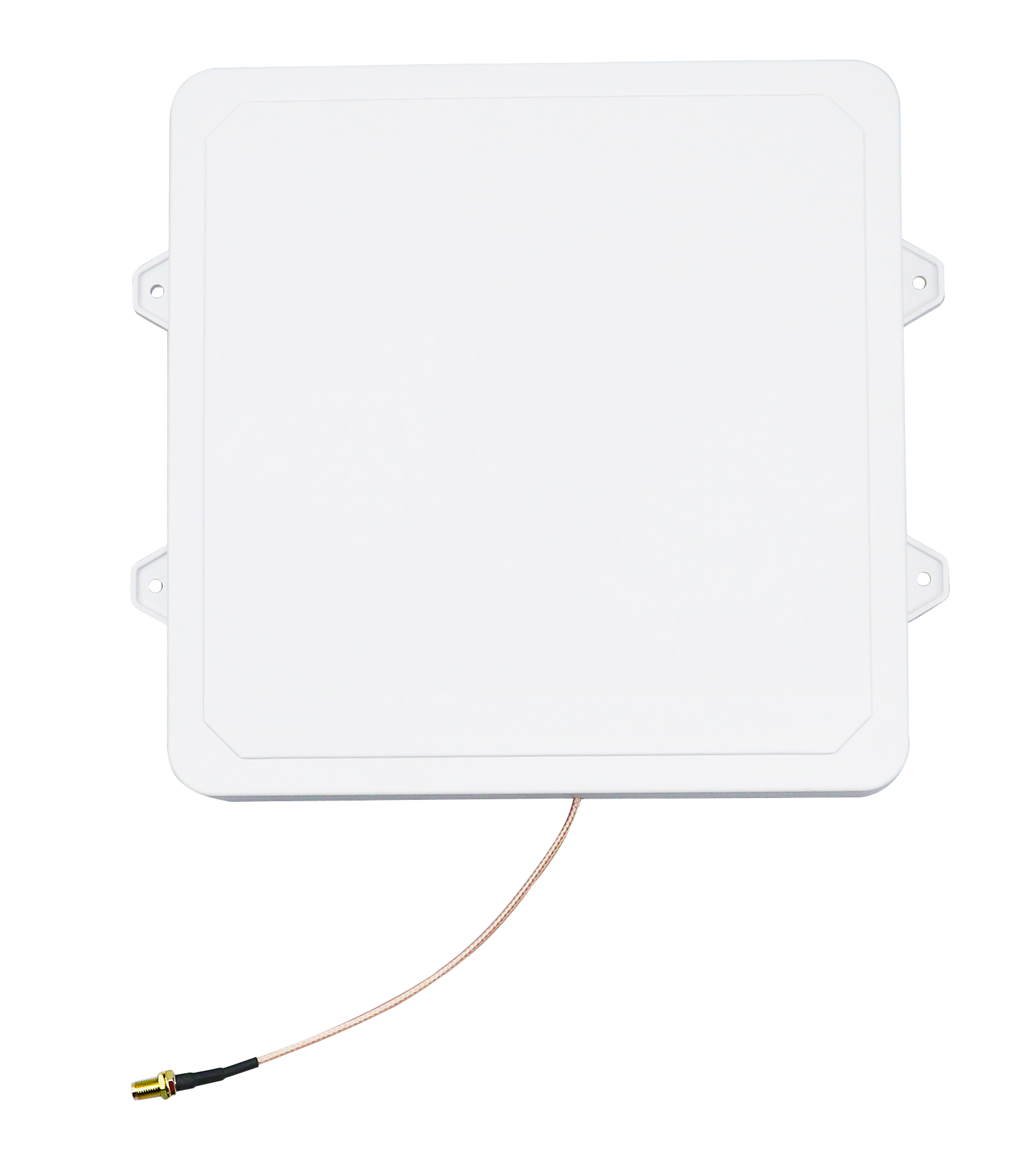
Protected installed antenna assemblies
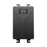
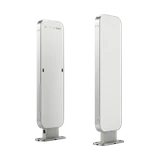
Enclosed UHF RFID Antennas
Enclosed UHF RFID antennas place the antenna structure inside a protective housing for wall, ceiling, machine, cabinet and exposed fixed-reader installations.
- Available with model-specific polarization, gain and field pattern
- Confirm enclosure protection, mounting holes and connector direction
- Match the housing and frequency version to the deployment site
Antenna comparison
Compare UHF RFID Antennas by Read-Zone Behavior
Polarization, field type, gain and construction work together. Compare the intended read-zone behavior before selecting a specific antenna model.
| ANTENNA FAMILY | FIELD TYPE | POLARIZATION | READ-ZONE CHARACTER | BEST FOR | WHAT TO CONFIRM |
|---|---|---|---|---|---|
| Circularly Polarized | Far-field | Circular | Broader tolerance to tag orientation | Portals, conveyors and general fixed read points | Gain, mounting angle, tag distance and adjacent zones |
| Linearly Polarized | Far-field | Linear | Focused directional coverage | Known tag orientation, shelves, lanes and fixtures | Tag axis, antenna aim and installation repeatability |
| Near-Field | Near-field | Model dependent | Short controlled identification zone | Verification stations, smart cabinets and close item reads | Object gap, tag construction, metal, liquid and boundary |
| PCB | Near- or far-field by design | Configurable | OEM-defined coverage inside equipment | Cabinets, kiosks, machines and embedded readers | Enclosure, footprint, ground plane, feed and cable path |
| Enclosed | Model dependent | Circular or linear | Protected installed read point | Wall, ceiling, machine and exposed installations | IP protection, mounting, gain, frequency and connector |
Selection logic
What to Confirm Before Choosing a UHF RFID Antenna
Confirm the required read zone, tag behavior, RF environment and installation path before choosing antenna gain or housing style.
Read-zone shape
Define the intended width, depth, direction and boundary of the RFID read point.
Tag orientation
Confirm whether tags remain aligned or rotate as objects move through the read zone.
Field type
Choose a near-field zone for close controlled reads or far-field coverage for greater distance.
Antenna gain
Match gain to the required field pattern and distance rather than selecting the highest value automatically.
Regional frequency
Confirm the antenna version for the deployment region and the reader frequency configuration.
Mounting and validation
Review connector, feeder-cable loss, mounting angle, surrounding materials and the actual tagged object.
Read-zone workflows
Build the Antenna Layout Around the Operating Point
Use antenna placement and field control to convert the reader output into a defined RFID checkpoint rather than an uncontrolled area of coverage.
Portal and conveyor checkpoints
Use directional antenna placement to capture tagged cartons, totes, pallets or assets while controlling overlap with adjacent lanes.
Shelves, workstations and cabinets
Use near-field or compact antennas when the read boundary must remain close to a shelf, tray, desktop or cabinet compartment.
Machine and OEM integration
Use PCB or enclosed antenna configurations where the equipment enclosure, cable routing and installation geometry are part of the final design.
FAQ
UHF RFID Antenna Questions
What does a UHF RFID antenna do?
The antenna transmits and receives RF energy between the RFID reader and UHF RFID tags. Its polarization, gain, field pattern and placement shape the actual read zone.
Should I choose circular or linear polarization?
Use circular polarization when tag orientation varies. Use linear polarization when tag alignment is known and a more focused directional field is useful.
What is the difference between near-field and far-field antennas?
Near-field antennas support short controlled identification zones. Far-field antennas are used when the read point requires broader directional coverage and greater distance.
Does a higher-gain RFID antenna always provide a better result?
No. Higher gain changes the field pattern and may increase unwanted reads or reduce coverage in other directions. The antenna must match the actual read-zone geometry.
How do I choose the correct regional frequency?
Confirm the country of deployment, reader frequency configuration and antenna frequency version before ordering or validating the system.
What should be tested before installing the antenna layout?
Test the actual tag, object material, distance, orientation, movement, mounting angle, cable length, nearby metal and adjacent read zones before scaling the installation.
Project guidance
Need help matching a UHF RFID antenna to the read point?
Send the tagged object, required distance, read-zone dimensions, tag orientation, mounting position, regional frequency, reader model and installation environment. Raylink can review the appropriate antenna family and validation path.