
IP67 Vehicle-Mounted UHF RFID Reader
RLFL-4P UHF RFID Forklift Reader
Automate pallet and material identification from the forklift. RLFL-4P connects up to four external antennas and uses sealed vehicle-mounted connections, wide-voltage power input and industrial I/O to capture compatible RFID events during pickup, putaway, transfer and loading workflows.


* Tag rate, read range and vehicle-read reliability depend on antenna selection, cable loss, tag design, tagged material, orientation, RF settings, nearby metal, movement speed, trigger logic and operating environment.
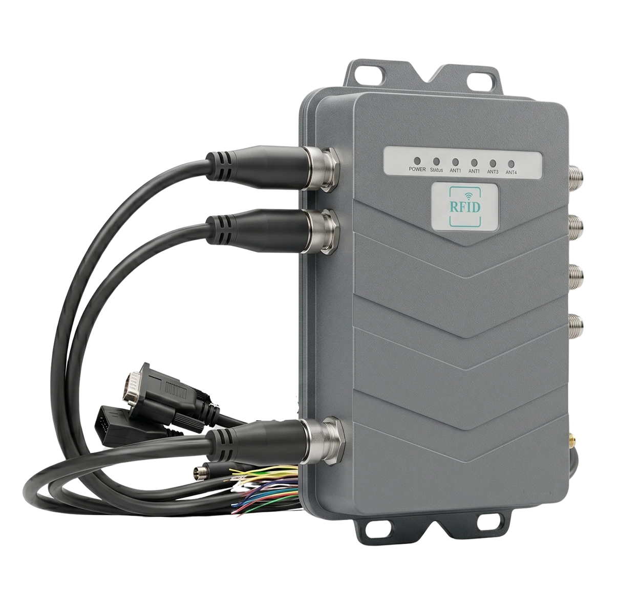
Why Use RLFL-4P?
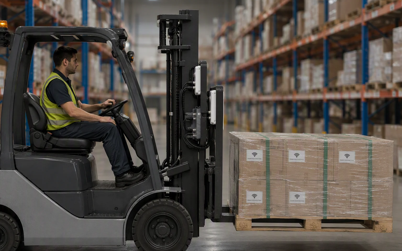
Move pallet identification into the normal forklift workflow
Use RLFL-4P when RFID capture should happen close to the forks, mast or handled load instead of requiring the driver to stop and scan every pallet manually.

Reduce repeated pallet scans
Capture compatible pallet, container or material tags during pickup, transfer, putaway or loading—reducing repeated barcode and item-by-item scanning.

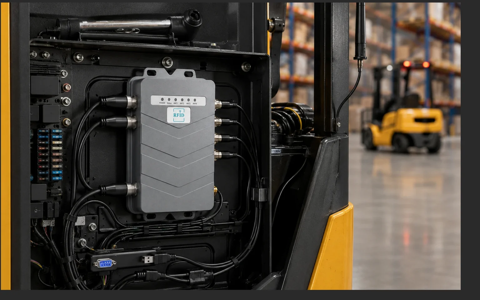
Protect vehicle-mounted connections
Use an IP67 aluminum enclosure and locking aviation connectors to protect the reader, power, communication and control wiring in dusty or wet industrial environments.

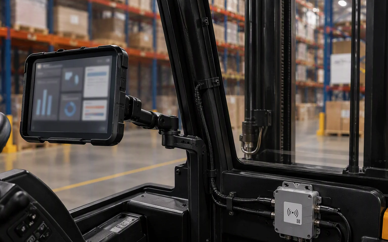
Connect events to warehouse systems
Send tag data to a vehicle terminal, warehouse application, WMS, MES, middleware or custom host through the supported wired or wireless interfaces.
Before / After
From stop-and-scan verification to forklift-mounted RFID capture
Replace a separate manual scanning step with a configured read area that captures compatible tags while the operator performs the normal material-handling task.
Manual pallet verification
Five repeated actions for each load

The operator interrupts the handling task and completes a separate identification step for every pallet or container.
RLFL-4P RFID capture
Three stages in the configured handling workflow
RLFL-4P captures and transmits RFID data. Pallet-to-task matching, location confirmation, route logic, exception handling and WMS/MES updates must be implemented in the connected vehicle terminal, host application, middleware or business system.
Forklift-Mounted RFID Capture
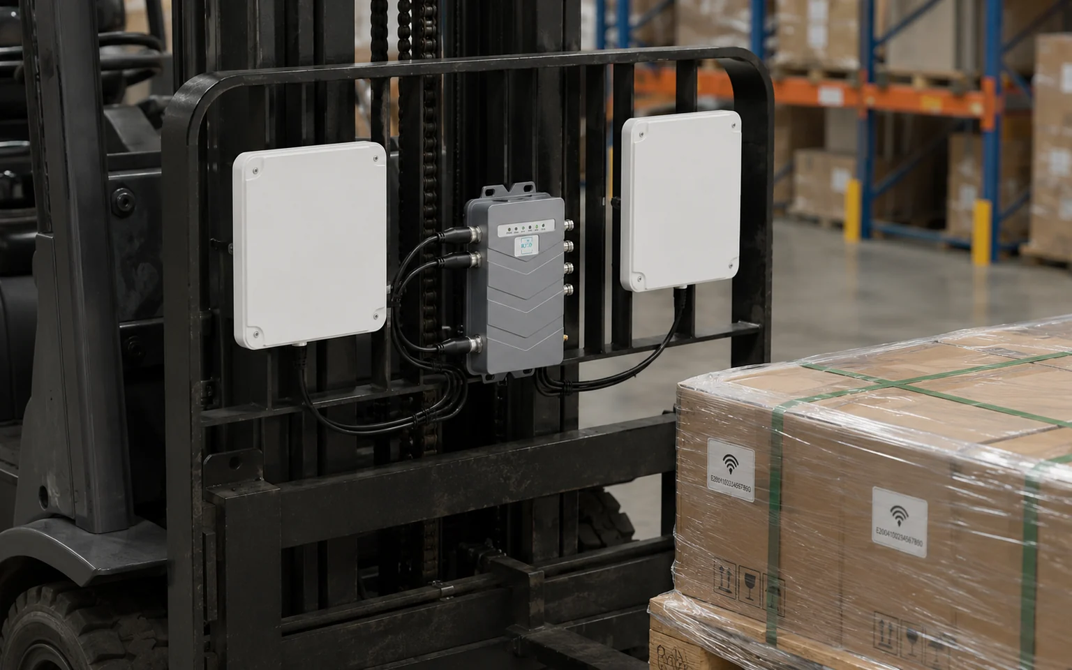
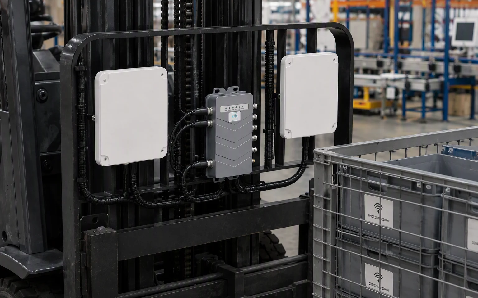
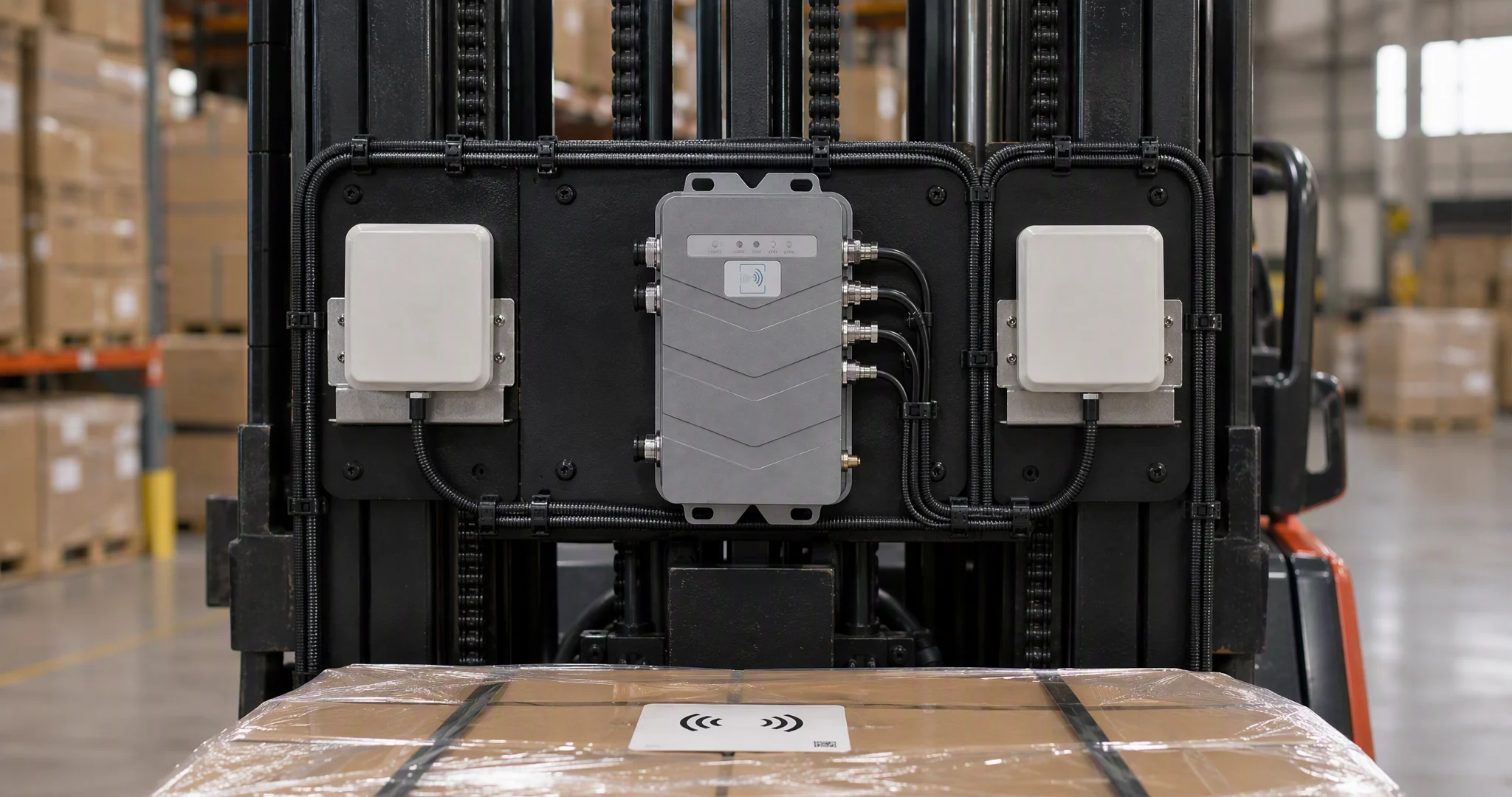
Position four external antennas around the forks, mast and handled load
Use the four RLFL-4P antenna ports to build a vehicle-specific read area. Antennas may be positioned around the load-handling structure according to the pallet tag position, forklift geometry, cable route and intended capture direction.
Route each external antenna toward the handled pallet, container, material or vehicle-side detection area required by the workflow.
Fork & Load Area
Position an antenna close to the pallet or container being picked up, carried or placed.
Mast-Side Coverage
Use a protected mounting position around the mast according to movement clearance and metal structure.
Left / Right Load Coverage
Use multiple antennas when the pallet tag may appear on different sides or orientations.
Approach or Transfer Point
Configure an antenna toward the intended pickup, transfer, staging or loading direction.
Four antenna ports do not automatically create four isolated read zones. Real separation depends on antenna pattern, position, shielding, RF power, cable loss, forklift metal, load material, tag orientation, spacing and site conditions.
Forklift RFID System Architecture
Move pallet identification from the vehicle to the warehouse workflow
RLFL-4P captures compatible tag responses. Trigger logic, task validation, location context, storage and business actions belong in the connected vehicle terminal, controller, middleware or warehouse system.
Tagged Pallet or Container
A compatible UHF RFID tag enters the configured vehicle-mounted read area.
External Antennas
The selected antenna positions create the project-specific RF coverage around the load.
Trigger or Vehicle Signal
A sensor, switch, vehicle signal or host command starts the approved read workflow.
RLFL-4P Reader
RLFL-4P processes compatible tag responses and sends the captured data outward.

Vehicle Terminal or Controller
The connected computer or controller receives the reader event and applies project logic.
WMS / MES / Warehouse App
The business platform records or acts on the validated pallet, task or movement event.
Vehicle & System Integration
Connect antennas, vehicle power, trigger signals and host communication
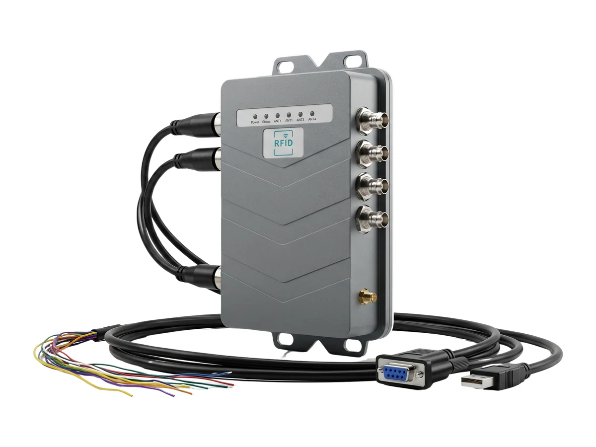
Use the RLFL-4P sealed cable system and supported interfaces to integrate RFID capture with sensors, vehicle terminals, industrial controllers, status devices and warehouse software.
-
01
DC 9–30 V Power Input
Connect RLFL-4P through the approved vehicle-power architecture and required electrical protection.
-
02
Ethernet and RS-232
Connect a vehicle terminal, industrial computer or host controller through the supported wired interface.
-
03
RS-485 and Wiegand
Use the supported industrial or access-control signals after confirming the final connector pinout.
-
04
Wi-Fi and Bluetooth
Use the listed wireless communication options after confirming the ordered hardware and firmware version.
-
05
4 Inputs + 4 Relay Outputs
Connect supported trigger, state, warning-light, buzzer or external-control signals.
Locking aviation connectors
Route power, communication and I/O through a protected vehicle-mounted cable system.
Four optocoupler inputs
Receive supported trigger or state signals from sensors, switches, vehicle controllers or external PLCs.
Four relay output channels
Support approved lights, buzzers or external equipment within the stated DC 0–30 V / 1 A output rating.
Wired and wireless communication
Use Ethernet, serial, Wi-Fi or Bluetooth according to the vehicle terminal and host-system design.
The final connector map, cable pinout, harness length, unused-port sealing method and included accessories must be confirmed against the ordered RLFL-4P production revision.
Supporting Features
Built for protected vehicle mounting and configurable RFID capture
Match the RLFL-4P enclosure, RF configuration, communication method and vehicle wiring to the actual forklift, tags, loads and warehouse workflow.
IP67 aluminum enclosure
Use the protected enclosure and correctly installed sealed connectors in dusty, wet or frequently cleaned industrial environments.

Up to 33 dBm with 1 dB steps
Tune output power around the antenna, cable, tag, forklift metal, read distance and intended target zone.

Tag filtering and RSSI support
Use the listed filtering and signal-strength data within the approved host workflow to improve project-specific event handling.

DC 9–30 V and −20 °C to +70 °C
Integrate RLFL-4P within the stated power and temperature limits after reviewing vehicle transients, cable routing and site conditions.

Applications
RFID workflows for pallet handling, loading and material movement
Use RLFL-4P where pallet or container identification should happen close to the vehicle and feed a connected warehouse, production or logistics workflow.
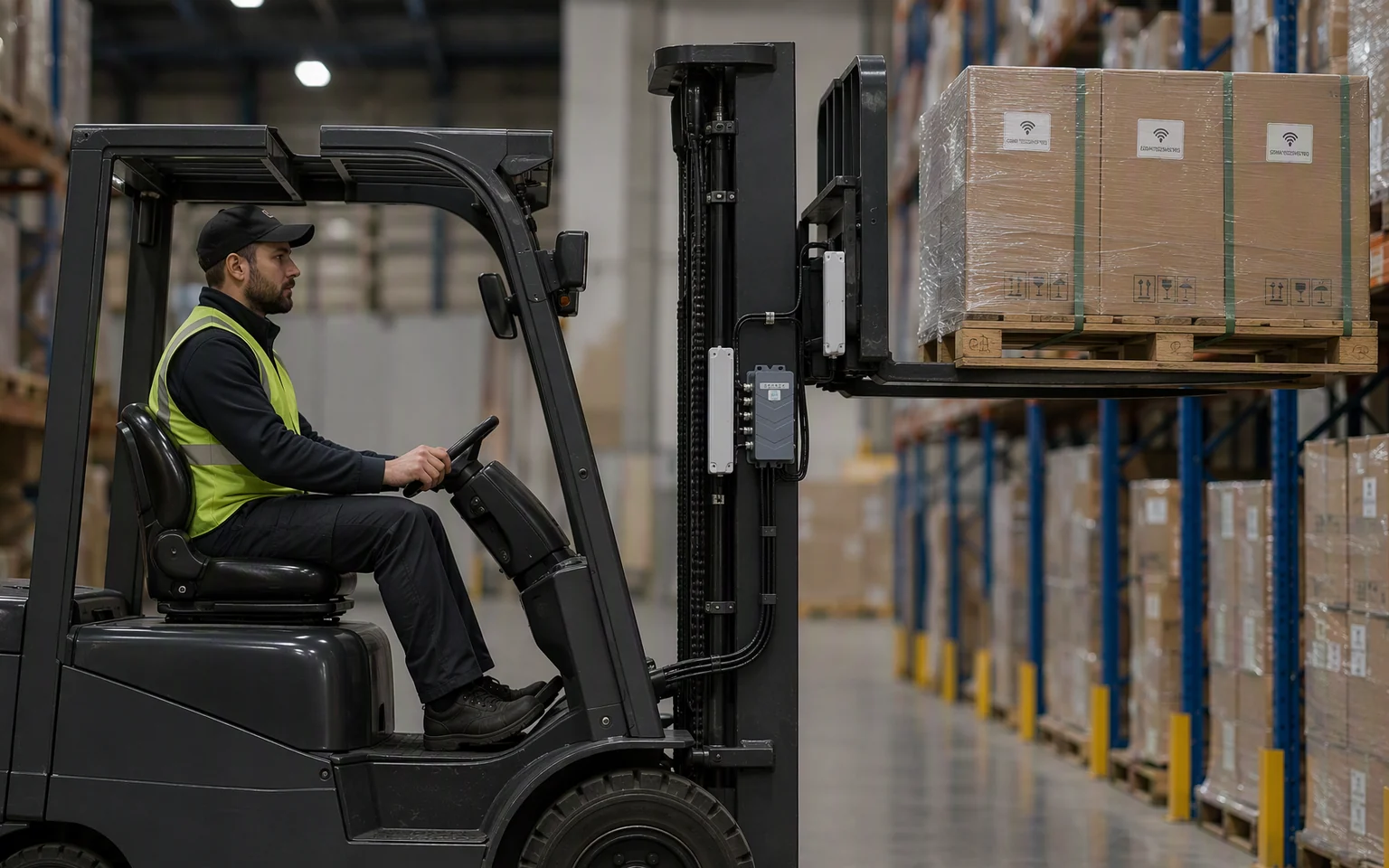
Pallet Pickup & Putaway Verification
Capture the handled pallet ID and pass it to the host workflow for task, pallet or destination validation.
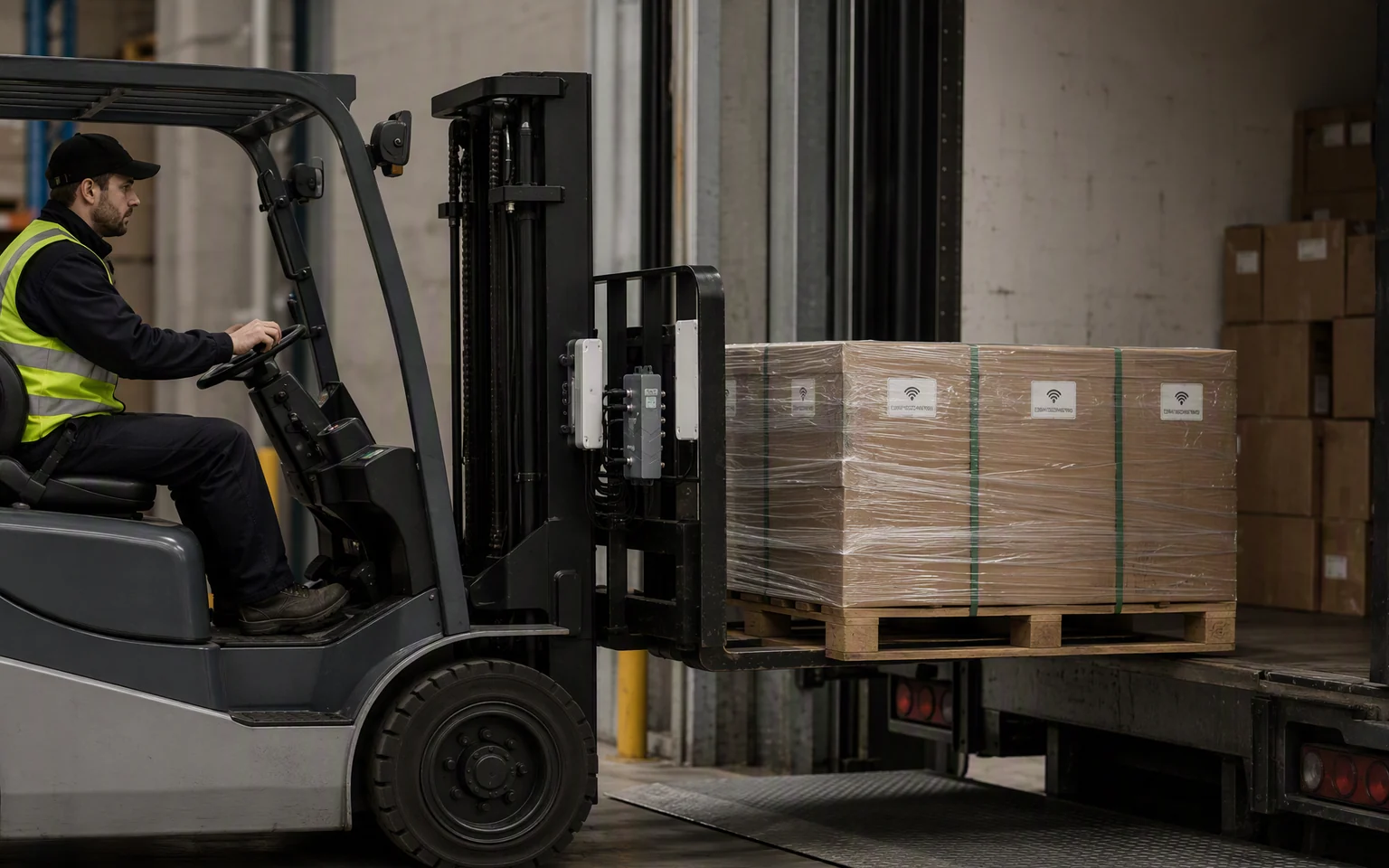
Loading & Unloading Verification
Collect compatible RFID events during dock transfer, trailer loading, unloading, staging or outbound preparation.
Material, WIP & Container Movement
Track tagged raw materials, work-in-process carriers, returnable containers, cages or reusable pallets through connected plant workflows.
Deployment Guidance
Design around the forklift, antenna, tag, power and movement
RLFL-4P does not create a controlled pallet-read zone by itself. Forklift metal, antenna position, tag placement, cable routing, trigger timing, RF power, load materials and vehicle motion determine actual performance.
Start with the handling task and target pallet, then select the antenna positions, trigger method, cable route and host integration around the real vehicle.
Account for the forks, mast, carriage, safety clearances, tag side and likely pallet orientations.
Confirm vehicle power quality, electrical protection, connector locking, abrasion protection, bend radius and cable movement.
Test the actual tags, pallets, materials, vehicle, approach direction, trigger timing, speed and neighboring inventory.
Specifications
RLFL-4P technical specifications and interface details
Review the supplied RFID performance, antenna connections, communication options, industrial I/O, vehicle power range, enclosure and environmental limits before project selection.
| RFID Performance | Working Frequency | FCC: 902–928 MHz; ETSI: 865.6–867.6 MHz; China: 920–925 MHz |
|---|---|---|
| Air Protocols | ISO/IEC 18000-6B and ISO/IEC 18000-6C / EPC Class 1 Gen 2 | |
| RF Output Power | Up to 33 dBm ±1 dB | |
| Power Adjustment | 1 dB steps | |
| Tag Read Speed | More than 500 reads per second under suitable conditions | |
| Stated Read Range | 0–20 m depending on antenna, cable, tag, RF settings, orientation, material, movement and environment | |
| Stated Write Range | 0–10 m depending on antenna, cable, tag, RF settings, orientation, material and environment | |
| Antenna & Data | Antenna Ports | 4 external antenna ports |
| RF Connector Type | Confirm final connector nomenclature before publication | |
| Reader Data Features | Tag-data filtering and RSSI are listed; DRM and simultaneous identification are also listed | |
| Communication | Ethernet | 10/100 Mbps auto-negotiation |
| RS-232 | 9600, 19200, 115200 default and 460800 optional baud rates | |
| RS-485 | Supported; confirm final aviation-connector pinout | |
| Wireless | Built-in Wi-Fi and Bluetooth are listed; confirm versions and ordered configuration | |
| Wiegand | Listed as supported; confirm signal direction, voltage and final pinout | |
| Automation I/O | Optocoupler Inputs | 4 channels |
| Relay Outputs | 4 channels, DC 0–30 V / 1 A | |
| Vehicle Connector System | Locking aviation connectors and cable harness; confirm each connector function and included cable set | |
| Power & Physical | Operating Voltage | DC 9–30 V |
| Power-Supply Capacity | Greater than 30 W specified | |
| Operating Consumption | Approximately 13 W at 33 dBm RF output | |
| Dimensions | 206 × 123 × 41 mm | |
| Weight | 0.8 kg | |
| Enclosure | Aluminum alloy, IP67 | |
| Environment | Operating Temperature | −20 °C to +70 °C |
| Storage Temperature | −40 °C to +85 °C | |
| Humidity | 10–95% RH, non-condensing |
Support & Documentation
Technical resources for vehicle installation and system integration

RLFL-4P Product Datasheet
Review RFID performance, communication interfaces, I/O, power, dimensions, environmental limits and ordering details.
Request datasheet →Cable & Pinout Guide
Review the aviation connectors, power, Ethernet, serial, Wiegand, input, relay-output and grounding requirements.
Request pinout guide →Forklift Integration Review
Review the forklift, load, tag, antenna positions, power source, trigger method, cable route and host workflow before deployment.
Discuss integration →Integration FAQ
RLFL-4P selection, mounting and workflow questions
What makes RLFL-4P suitable for forklift installation?
RLFL-4P combines an aluminum IP67 enclosure, locking aviation connectors, four external antenna ports, DC 9–30 V input, wired and wireless communication, and industrial I/O. The final installation still requires approved mounting, electrical protection, cable routing and validation.
Is the complete RLFL-4P reader and cable system waterproof?
The supplied specification lists IP67 for the RLFL-4P enclosure. Complete installed protection depends on using the specified connectors, mating plugs, seals, cables and unused-port caps correctly.
How many external antennas can RLFL-4P connect?
RLFL-4P provides four external antenna ports. Select the final antenna count and position around the forks, mast, handled load, tag location, cable route and target direction.
Can RLFL-4P identify only the pallet currently being handled?
That is a system-design objective, not an automatic guarantee. Use suitable antennas, controlled RF power, careful mounting, shielding where practical, trigger timing, tag placement and host logic to reduce adjacent reads.
What affects tag capture while the forklift is moving?
Performance depends on antenna pattern and polarization, tag design, pallet material, tag orientation, cable loss, RF power, vehicle metal, movement speed, trigger timing, distance, interference and nearby tagged inventory.
Can a sensor or vehicle signal trigger RLFL-4P reading?
The supplied specification lists four optocoupler inputs. A sensor, switch, controller or vehicle-state signal may be used after the signal level, connector pinout, ownership and timing are confirmed.
How many input and output channels are available?
RLFL-4P is specified with four optocoupler inputs and four relay outputs. The relay outputs are listed for DC 0–30 V / 1 A.
Can RLFL-4P connect to a vehicle terminal or industrial computer?
Ethernet, RS-232 and RS-485 are listed, together with Wi-Fi and Bluetooth. Select the interface according to the terminal and host application, then confirm the final cable assembly and protocol.
Can RLFL-4P data be sent to WMS, MES or ERP software?
Yes, through a vehicle terminal, host application, middleware, industrial controller or custom integration. RLFL-4P should not be presented as a native WMS, MES or ERP connector unless a specific software connector is confirmed.
Does RLFL-4P support Wi-Fi and Bluetooth?
Built-in Wi-Fi and Bluetooth are listed in the supplied specification. Confirm the wireless versions, antenna configuration, operating mode and ordered hardware revision before publication or quotation.
What power supply does RLFL-4P require?
RLFL-4P is specified for DC 9–30 V, with power-supply capacity greater than 30 W. Vehicle installations should also review reverse-polarity protection, surge protection, vehicle transients, grounding, fusing and shutdown behavior.
How should RLFL-4P cables be routed on the forklift?
Keep cables away from pinch points, moving mast components, sharp edges, heat and driver controls. Use strain relief, abrasion protection, suitable bend radius, connector locking and service loops.
Should the stated read range of up to 20 m be the forklift design target?
Usually not. Forklift projects commonly need a controlled read area close to the handled load rather than maximum distance. Tune antenna placement and RF power to capture the intended pallet while reducing adjacent reads.
Does RLFL-4P support MQTT, local caching or edge applications?
No MQTT client, local event cache, on-reader database, edge runtime or business-rule engine is confirmed in the supplied specification. Implement these functions in a connected terminal, middleware or host system unless another firmware option is documented.
Which RLFL-4P regional frequency version should be ordered?
Select the version that matches the deployment region. The supplied specification lists FCC 902–928 MHz, ETSI 865.6–867.6 MHz and China 920–925 MHz. Confirm regulations and firmware before shipment.
Project Review
Confirm the RLFL-4P configuration for your forklift workflow
Share the forklift model, tagged loads, antenna positions, read trigger, movement speed, vehicle power, cable route, input and output signals, host interface, software environment, operating region and expected project quantity.