
UHF Integrated RFID Reader
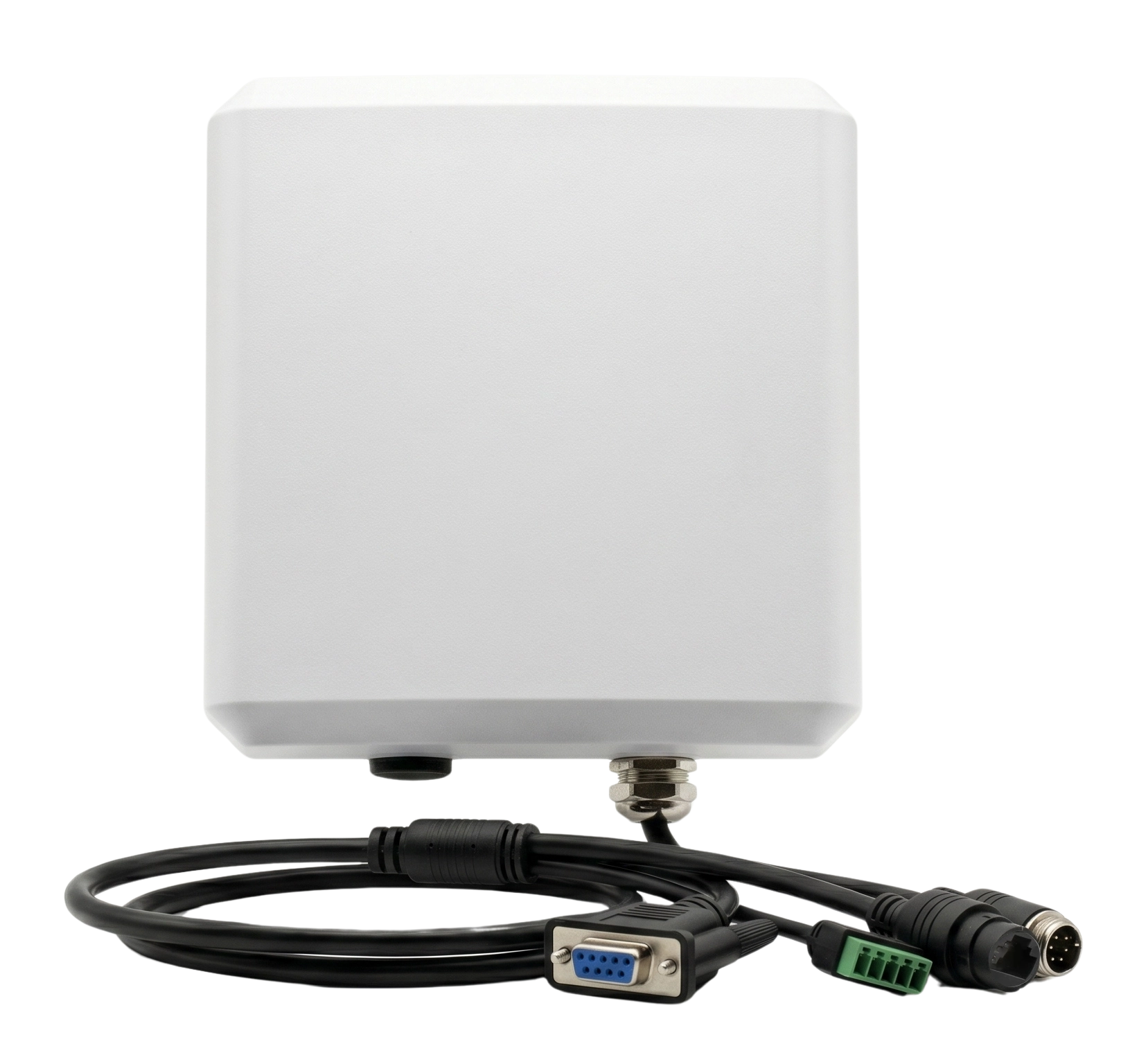
RLI-6dBi Integrated UHF RFID Reader
Automate tag capture at production, logistics and controlled-access checkpoints with a built-in 6 dBi circularly polarized antenna, adjustable RF power and industrial I/O.
Reduce repetitive manual scans, return identification data to the host system and trigger an immediate process response at one fixed RFID read point.
*Typical maximum measured with an E41 reference test tag, the built-in 6 dBi antenna and full RF output. Actual UHF RFID reader range depends on the tag, object, orientation, installation, regional settings and RF environment.
Operational Value
From Repetitive Manual Checks to Automated RFID Confirmation
The RLI-6dBi is designed for recurring identification points where the same detect, read, validate and respond sequence would otherwise require repeated operator interaction.
Operator-Dependent Checkpoint
Repeated action for every item or transfer

More repetitive interaction and more opportunities for missed or delayed records.
Automated Identification Checkpoint
Repeatable trigger, read and response sequence

Operational improvements depend on the complete deployment, including tag selection, read-zone validation, host software, process rules and user adoption. Quantified time, accuracy or labor savings should be published only when supported by project data.
Good Reasons
Why Choose the RLI-6dBi Integrated RFID Reader?
Four product-level reasons help system integrators determine whether this industrial UHF RFID reader matches the required checkpoint, regional frequency and control workflow.
Integrated 6 dBi Antenna
The UHF RFID reader and circularly polarized antenna are combined in one fixed enclosure for a self-contained read point.
Industrial Trigger and Control
Two optocoupler inputs receive external signals, while two relay outputs return results to compatible field devices.
EU or US Frequency Version
Select an antenna and RF configuration for European or US regional requirements instead of presenting one universal frequency setting.
Configurable Host Communication
Use serial communication and selected optional communication configurations to connect the RFID read point to the host system.
RFID Event Workflow
Turn Each Tag Read into an Immediate Process Response
The RLI-6dBi can sit inside a larger automation workflow: receive a trigger, capture tag data, pass the event to the host and return a response to the field.
Start a read cycle from a photoelectric sensor, PLC or another compatible control signal through either optocoupler input.
Send EPC, TID or user-memory data to the connected application for item identification, process verification or access decisions.
Use either relay output to activate a compatible light, buzzer, gate signal or other response defined by the integration.
Applications
Integrated RFID Reader Applications at Fixed Checkpoints
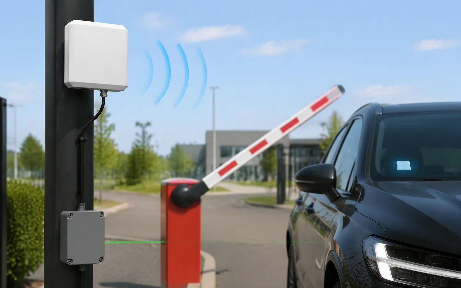
The RLI-6dBi is strongest where the tag path, reader position and trigger window can be defined and tested rather than used as a general-purpose mobile inventory tool.
 Manufacturing
Production Verification Point
Automatically confirm tagged components, tools or workpieces before the next production step, helping reduce repeated manual checks and data entry.
- Sensor or PLC trigger
- Host-side pass/fail validation
- Relay response to field equipment
 Logistics
Logistics Transfer Checkpoint
Capture tagged cartons, bins or assets as they move between storage, staging and dispatch areas, helping reduce missed transfer records.
- Fixed and repeatable travel path
- Automatic tag-event capture
- WMS, middleware or local host connection
 Access
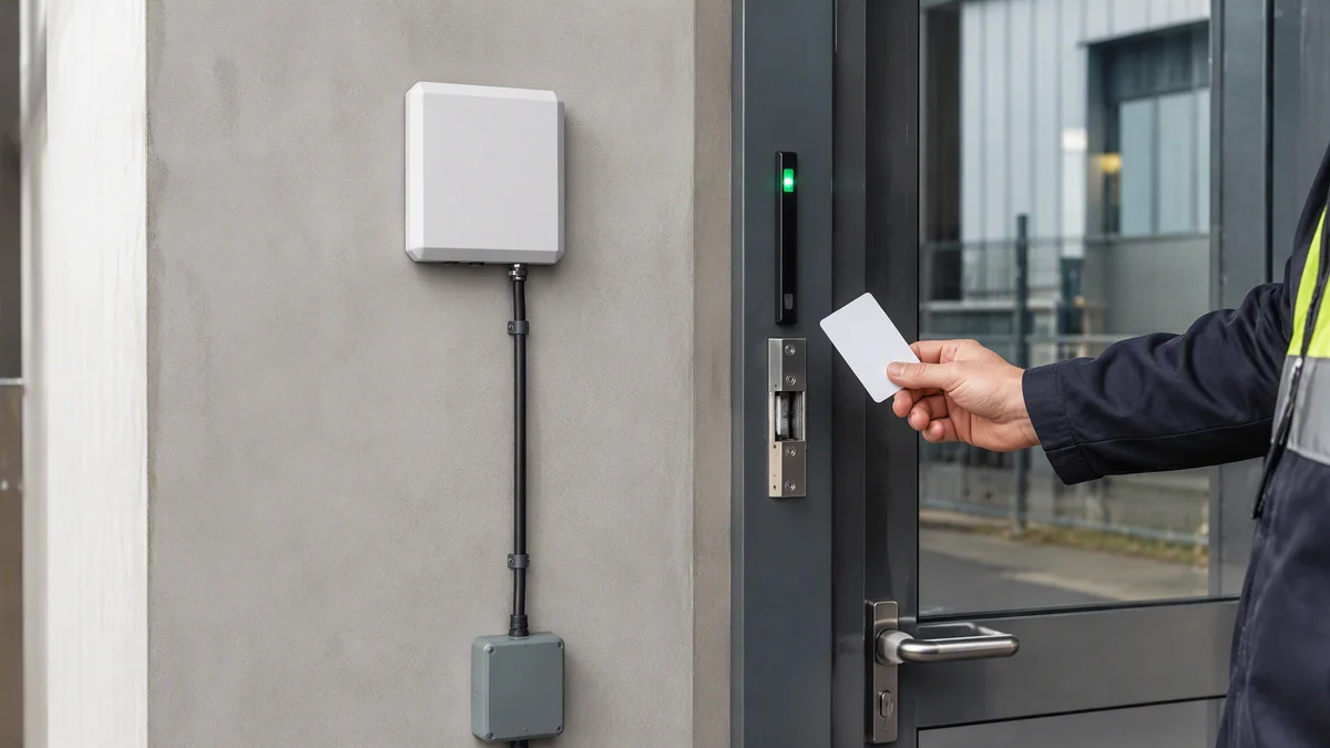
Controlled Access Identification
Return vehicle, personnel-card or asset identity to the connected access system for validation and further action.
- Defined lane or approach direction
- Consistent tag mounting position
- Host-controlled authorization decision
For wider lanes, longer-distance requirements or PoE deployment, evaluate the higher-gain RLI models. Final model selection must be validated with the actual tag, object, lane width and installation environment.
Read Performance
Understanding the UHF RFID Reader Range
The stated read range is a reference result, not a guaranteed working distance for every RFID tag or installation.
The antenna and reader are tested as one integrated RF system.
The typical maximum is based on the stated reference tag rather than every commercial tag format.
The maximum reference distance uses full output power and must remain within regional operating requirements.
Actual performance varies with tag antenna size and sensitivity, mounting material, tag orientation, reader angle, object movement, nearby metal or liquid, multipath reflection and RF interference.

Communication and I/O
Connect the RFID Read Point to the Control System
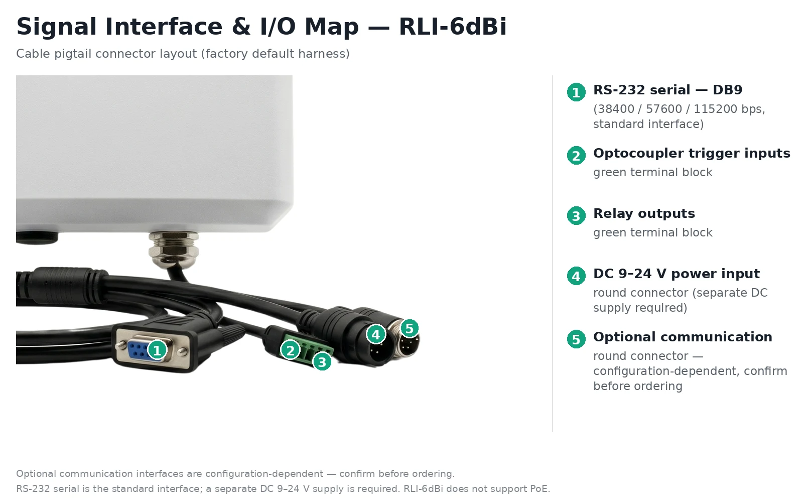
Specify the host interface, external trigger source, output action and DC power arrangement before ordering the final RLI-6dBi configuration.
-
1
Serial Communication
Supported baud rates: 38400, 57600 and 115200 bps.
-
2
Two Optocoupler Inputs
Receive trigger or control signals from compatible sensors, PLCs or external devices.
-
3
Two Relay Outputs
Return identification or validation results to compatible indicators, alarms or control circuits.
-
4
DC Power Input
Separate DC input is required. The specified operating range is 9–24 V DC.
-
5
Optional Communication Configuration
Confirm the required interface and cable arrangement when ordering; availability depends on the selected configuration.
Power boundary: RLI-6dBi does not support PoE. PoE is available only on selected 7–12 dBi integrated reader models.
Project Configuration
Configure the RLI-6dBi for the Actual Read Point
Frequency, tag performance, communication and installation conditions should be confirmed as one project configuration rather than selected as isolated specifications.
Technical Specifications
RLI-6dBi Specifications and Configuration Details
Confirm optional interfaces, supplied cable definitions and regional frequency before production ordering. The 6 dBi model requires separate DC power and does not support PoE.
| RF Performance | |
|---|---|
| Product type | Integrated UHF RFID reader |
| Air-interface protocol | ISO 18000-6C / EPC Class 1 Gen 2; ISO 18000-6B |
| Frequency configuration | European 860–868 MHz or US 902–928 MHz version |
| RF output power | 0–33 dBm, adjustable |
| Power adjustment | 1 dBm steps |
| Typical read range | Up to 6 m under stated reference test conditions |
| Reference test condition | Built-in 6 dBi circular antenna, E41 reference tag and full RF output |
| RSSI | Supported |
| Read/write areas | EPC, TID and user memory |
| Operating modes | Command, polling and trigger modes |
| Integrated Antenna | |
| Antenna gain | 6 dBi |
| Polarization | Circular polarization |
| Beamwidth | Horizontal 60° ±2° / Vertical 60° ±2° |
| VSWR | ≤1.3 |
| Impedance | 50 Ω |
| Front-to-back ratio | ≥25 dB |
| Communication and I/O | |
| Standard communication | Serial communication |
| Optional communication | Available by selected configuration; confirm before ordering |
| Baud rate | 38400 / 57600 / 115200 bps |
| Digital inputs | 2 optocoupler inputs |
| Control outputs | 2 relay outputs |
| Power and Environment | |
| Power input | DC 9–24 V |
| PoE | Not supported on RLI-6dBi |
| Operating temperature | -20°C to +55°C |
| Storage temperature | -40°C to +85°C |
| Operating humidity | <95% RH, non-condensing at +25°C |
| Enclosure rating | IP65 |
| Mechanical and Development | |
| Dimensions | 133 × 133 × 52 mm |
| Antenna cover | ASA, UV-resistant |
| Mounting pole diameter | Ø30–50 mm |
| SDK and demo | Available for integration and secondary development |
| Firmware upgrade | IAP supported |
IP65 refers to the specified reader enclosure. The installed system must use correctly sealed connectors, cable glands and mounting practices to maintain the intended environmental protection.
Design-In Views
Mechanical Drawing and Product Views
Use the drawing and connector views to review mounting space, cable routing and service access before final installation.
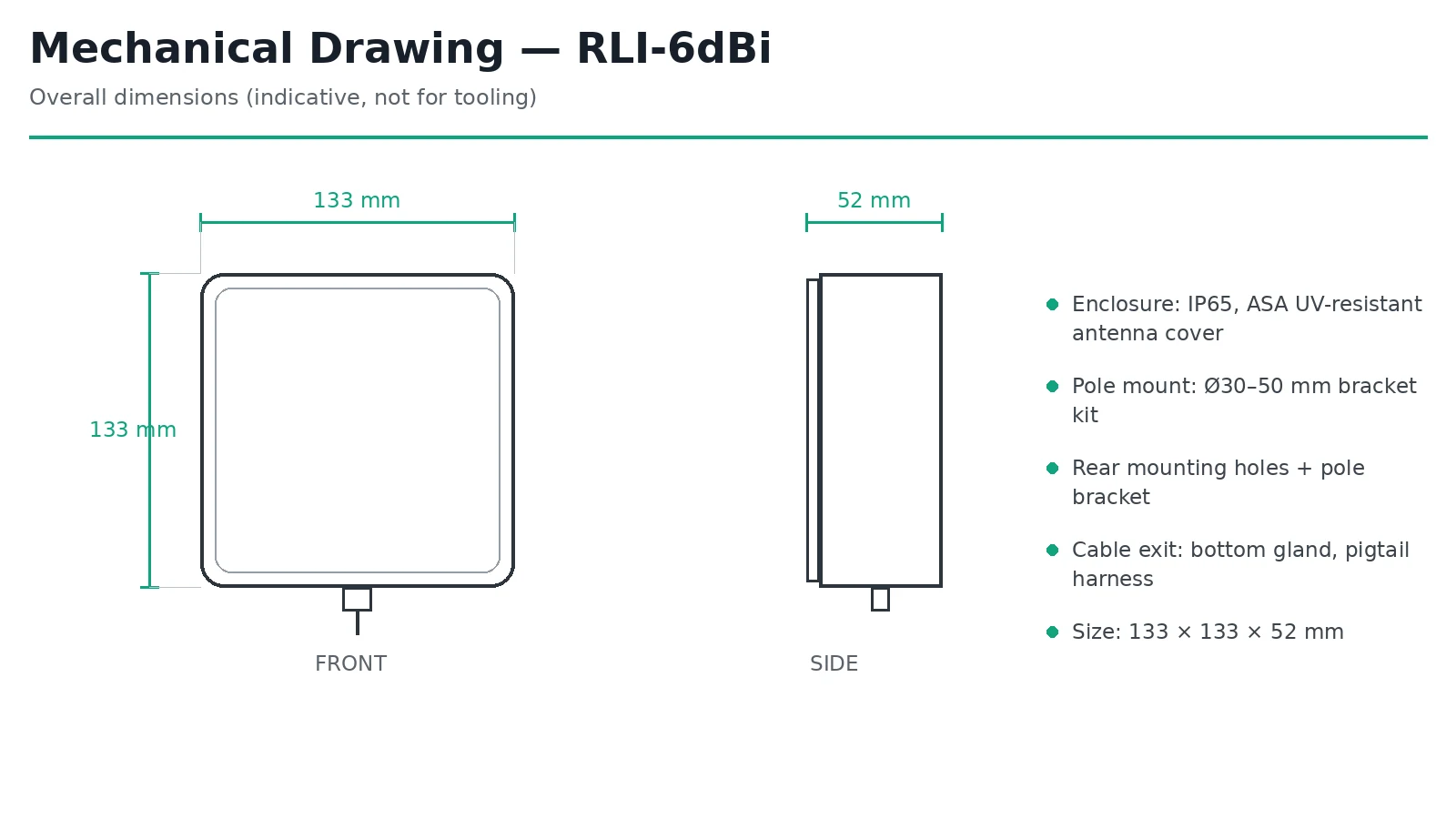
Mechanical Drawing

Front View

Rear and Cable View
Technical Resources
Resources for Evaluation and Integration
Request the files required to evaluate the RLI-6dBi, develop the host connection and review the mechanical installation.
Product Data Sheet
Review RF, antenna, communication, I/O, environmental and mechanical specifications.
Request Data SheetSDK and Demo Software
Start serial integration, reader configuration and secondary development with the available software resources.
Request SDKI/O and Mechanical Files
Confirm signal definitions, connector requirements, dimensions and the intended mounting arrangement.
Request Engineering FilesFAQ
RLI-6dBi Integrated UHF RFID Reader FAQ
What is integrated inside the RLI-6dBi?
The device combines a UHF RFID reader engine and a built-in 6 dBi circularly polarized antenna in one fixed enclosure, together with communication, input and relay-output connections.
Can the RLI-6dBi always read RFID tags from 6 meters?
No. Up to 6 m is a typical maximum measured with an E41 reference tag at full RF output. Actual distance depends on tag design, object material, orientation, reader placement and the RF environment.
Does the RLI-6dBi support PoE?
No. The RLI-6dBi requires a separate DC power connection. PoE is available only on selected 7–12 dBi integrated reader models.
Which regional frequency versions are available?
The antenna and RF configuration can be supplied for European 860–868 MHz or US 902–928 MHz requirements. Confirm the destination region before ordering.
Which serial baud rates are supported?
The supported baud rates are 38400, 57600 and 115200 bps.
How can the two inputs and two relay outputs be used?
The optocoupler inputs can receive external trigger signals. The relay outputs can return a result to compatible indicators, alarms, gate signals or other control circuits defined by the system integration.
Is the RLI-6dBi a complete RFID software solution?
No. It is integration-ready RFID hardware. Application logic, database processing, event filtering and workflow decisions are implemented by the connected host or customer software.
When should a higher-gain RLI model be considered?
Evaluate a 7–12 dBi model when the project requires a different coverage area, a higher-gain antenna or PoE. The final choice should be based on the actual tag and site test.
Project Configuration
Configure the RLI-6dBi for Your RFID Checkpoint
Send the deployment region, tag model, target object, required distance, communication interface, trigger source and intended output response for technical review.